if-then

Assertions of truth can usually be phrased in the form “if … then …”. Such assertions can be re-stated in many other equivalent ways. Doing so helps you to better understand these fundamental truths or to easily expose falsehoods.

Below are two infographics summarizing the main ways to re-phrase if-then statements. Click here for a PDF document that gives details (especially explaining what is meant by the word “implies”). The PDF also offers additional examples and in-class exercises.

This example is trivial to help make it clear that truth of one implies truth of all others (and untruth of one would also imply untruth of all others). But these sorts of rephrasings can give you unexpected insights when applied to nontrivial if-them statements. Try it on a few of the examples in the full PDF document!

Truss myths and analysis

This structure would be a stable truss even though it’s not made entirely of triangles.

I’ve shared my undergrad lecture slides on “myths in truss analysis” so often that I’m making my life easier by now sharing them more broadly: http://csm.mech.utah.edu/TrussMythsAndTrussExamples.pptx. Please let me know if you see errors!


Material Property Terminology Tutorial

If you do a web search on the difference between various terms in materials engineering, you will encounter a mind-boggling array of misinformation. The following infographic summarizes basic differences between the following terms: stiffness, compliance, yield strength, rupture strength, ultimate strength, hardening, softening, ductility, rupture strain, resilience, and toughness.  Of course no real stress-strain diagram looks like any of these, but the sketches are exaggerated to help illustrate the terminology.

MaterialPropertyTerminologyShadow

Copyright statement: This infographic may be used freely as long as it isn’t altered in any way.

Keep reading for important clarifications!

Continue reading

Tips for writing literature reviews

This posting aims to help graduate students write a good literature review for their qualifying exam, proposal, or thesis.

In the Department of Mechanical Engineering at the University of Utah, the qualifier examination is not a proposal, so there is no expectation that your Qual paper should propose new research.  Your literature review should, however, critically assess existing research in the subject area by pointing out specific limitations of (and, if applicable, errors in) existing published work.   The qualifier paper is meant to show that you can string together a coherent scholarly discussion.   The qualifier paper can have a fairly broad literature review as long as it still limits attention to mechanical engineering topics. The proposal document, on the other hand, should include a literature review that is more tightly related to your proposed research, as your aim is to convince the committee that your proposed work is (1) important to the field of Mechanical Engineering and (2) has not been done. The thesis document should include an updated literature review that suggests no one else has accomplished the same thing during the time you were working on it (or prior to your efforts, but inadvertently overlooked in your original literature review). The final thesis literature review should also thoroughly compare/contrast your own accomplishments with alternative approaches in contemporary literature.

Continue reading

Streamlines, Streaklines, Pathlines, and Gridlines

GridStreamStreakPath

The above animation aims to be a slight improvement over one on Wikipedia, which (incidentally) does not correctly describe the velocity field that it is depicting. The Wikipedia image doesn’t show a checkerboard of moving material, nor does it have a nice depiction of streamlines.

Before describing this animation, it might be helpful to look at a simpler motion (a rolling body) in order to review the difference between streamlines, streaklines, and pathlines. Consider a simple rigid body consisting of a disk of small radius (shown in gray below) along which it rolls along a tabletop, along with a larger-radius extension of the body (shown in color below) which can dip down below the table surface (as if there is a slot cut into the table so that part of the body rolls under it).

STREAMLINES: These are tangent to the instantaneous velocity field.  For a rolling rigid body, the motion is always circular about the instantaneous center of rotation at the bottom of the wheel. Accordingly, this image shows the streamlines at various points in time as the disk rolls along:

particleStreamLineRolling

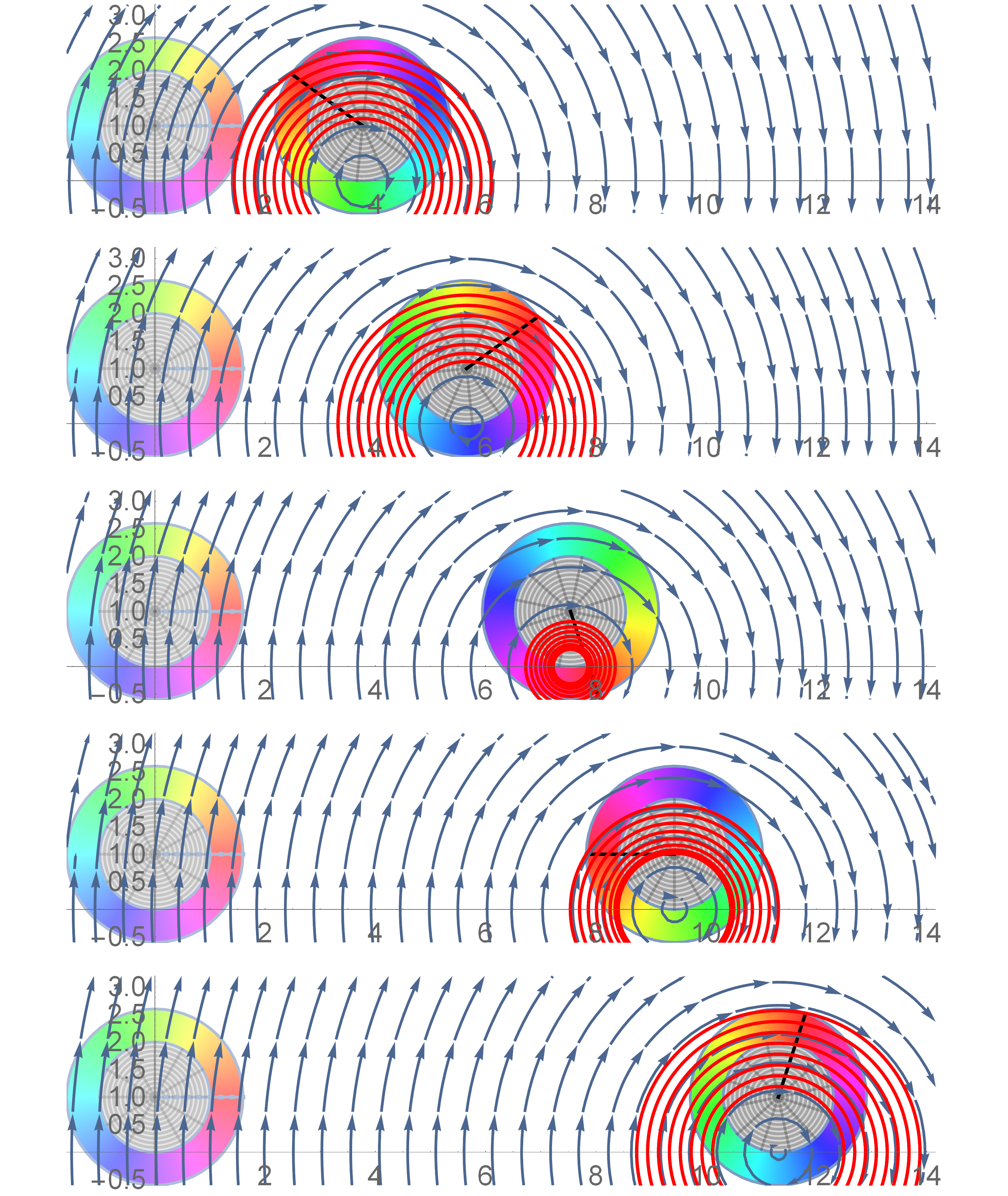
This image of streamlines is drawn not just on the body itself but also on its “virtual extension” in order to emphasize that (for rigid rolling) the instantaneous velocity is circular around the instantaneous center of rotation (bottom of the wheel). A particular set of streamlines is drawn in red. These are the ones that pass through a set of points that are evenly distributed on a spoke of the wheel (shown in black).

STREAKLINES: These are the lines you would see if a magic gremlin were to sit at a given location in space and “spraypaint” the material as it passes by.  Suppose that an assembly line of gremlins (located where you see the dots in the first image) are pointing their spray paint cans at the body while it rolls past. Then they would form the black streaklines shown here at various times:

streaklinesOnBefore

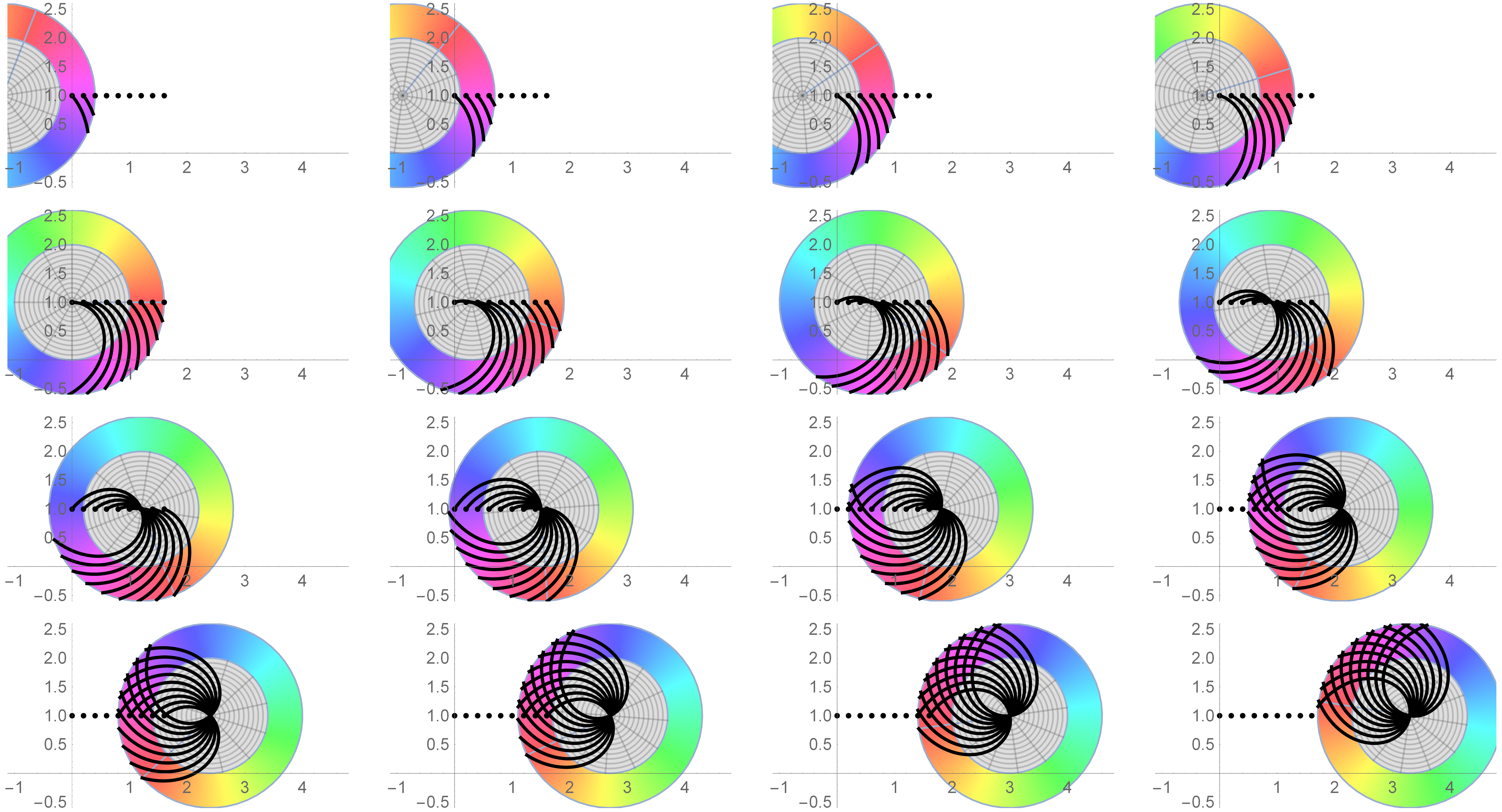
Important: The streaklines are made by gremlins who are sitting still and spraying material as it passes by.

PATHLINES: Are made by gremlins who “ride” with the material, spraying a record of where they have been (as if we were watching the rolling body from behind a window, and those whacky gremlins would spray paint onto the window as they pass by). Accordingly, here are the pathlines for group of gremlins who were initially coincident with the gremlins in the above streakline plot:

particlePathLineRolling

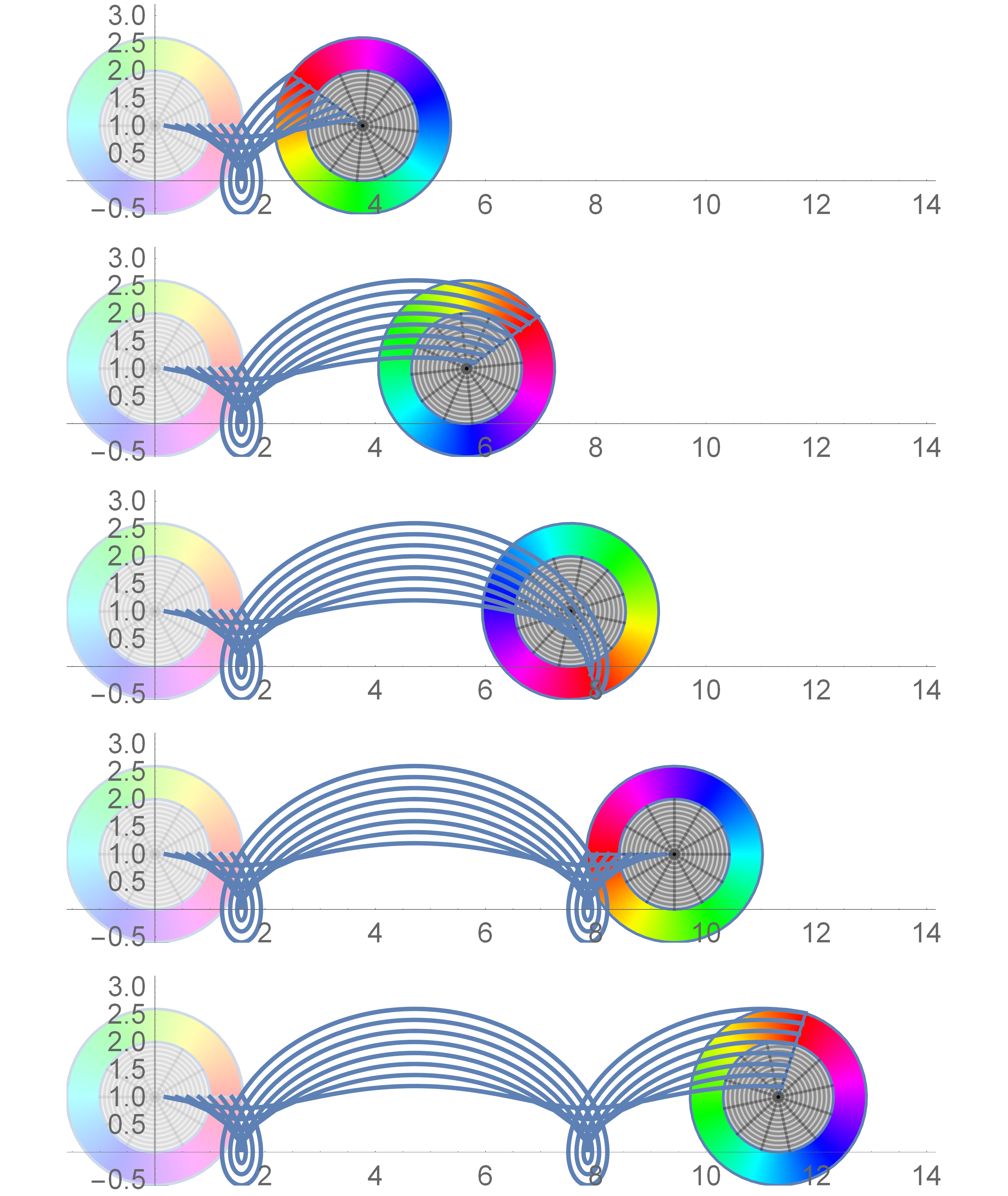
GRIDLINES are any set of lines that are painted on the body like tattoos. Such lines move with the body (like a tattoo).


Continue reading

von Mises: cylinder, circle, or ellipse?

The answer is…all of the above!   The von Mises cylinder is centered about the {1,1,1} direction in principal stress space.  The ellipse that we learn about as undergrads applies only to plane stress (where the third principal stress is zero), and this is just the intersection of the cylinder with the plane.  The circle applies to the octahedral plane, which is the view of the cylinder down its {1,1,1} axis.  This animation should clarify what is going on:

MisesCylinderAndMisesEllipse


PowerPoint slides for Mohr’s circle

The link below provides a collection of slides used to explain Mohr’s circle in an undergraduate mechanics course at the University of Utah.  If you use a Mac, it is unlikely that these will render properly (so go sit at a PC in your university computer lab to look at them).  Make sure to use slideshow mode, as these have many animations!

MohrCircleFiles  (zip file contains two PPT lectures and one Mathematica file)