

Tag Archives: verification
The kinematic anomaly in MPM
The following Material Point Method (MPM) simulation of sloshing fluid goes “haywire” at the end, just when things are starting to settle down:

(if the animated gif isn’t visible, please wait for it to load)
F-tables for prescribed deformation

Motion without superimposed rotation
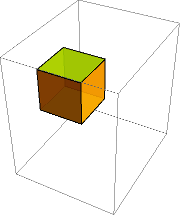
Same deformation with superimposed rotation
When developing constitutive models, it is crucial to run the model under a variety of standard (and some nonstandard) homogeneous deformations. To do this, you must first describe the motion mathematically. As indicated in http://csm.mech.utah.edu/content/wp-content/uploads/2011/03/GoBagDeformation.pdf, a good way to do that is to give the deformation gradient tensor, F. The component matrix [F] contains the deformed edge vectors of an initially unit cube, making this a very easy to way to prescribe deformations.
Aldridge (AKA Blake) spherical source verification test for dynamic continuum codes
This post has the following aims:
- Provide documentation and source code for a spherically symmetric wave propagation in a linear-elastic medium.
- Tell a story illustrating how this simple verification problem helped to validate a complicated rate-dependent and history-dependent geomechanics model.
- Warn against believing previously reported material parameters, since they might have been the result of constitutive parameter tweaking to compensate for unrelated errors in the host code. Continue reading
Streamline visualization of tensor fields in solid mechanics

Stress net view of maximum shear lines inferred from molecular dynamics simulation of crack growth. Image from http://doi.ieeecomputersociety.org/10.1109/VIS.2005.33

Brazilian stress net before and after material failure. Colors indicate maximum principal stress (showing tension in the center of this axially compressed disk). Lines show directions of max principal stress.
A stress net is simply a graphical depiction of principal stress directions (or other directions derived from them, such as rotating them by 45 degrees to get the maximum shear lines.) Continue reading
Annulus Twist as a verification test
Illustrated below is the solution to an idealized problem of a linear elastic annulus (blue) subjected to twisting motion caused by rotating the T-bar an angle 
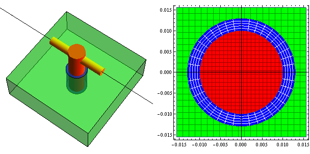
This simple problem is taken to be governed by the equations of equilibrium 
Course offering: ME 7960 (special topics) Computational Constitutive Modeling

Constitutive modeling refers to the development of equations describing the way that materials respond to various stimuli. In classical deformable body mechanics, a simple constitutive model might predict the stress required to induce a given strain; the canonical example is Hooke’s law of isotropic linear elasticity. More broadly, a constitutive model predicts increments in some macroscale state variables of interest (such as stress, entropy, polarization, etc.) that arise from changes in other macroscale state variables (strain, temperature, electric field, etc.).
Constitutive equations are ultimately implemented into a finite element code to close the set of equations required to solve problems of practical interest. This course describes a few common constitutive equations, explaining what features you would see in experimental data or structural behavior that would prompt you to select one constitutive model over another, how to use them in a code, how to test your understanding of the model, how to check if the code is applying the model as advertised in its user’s manual, and how to quantitatively assess the mathematical and physical believability of the solution.
Research: Weibull fragmentation in the Uintah MPM code

Tough disk impacting brittle disk
Below are links to two simulations of disks colliding. The first is elastic and the second uses a fracture model with spatially variable strength based on a scale-dependent Weibull realization. Both take advantage of the automatic contact property of the MPM.
WeibConstMovie: disks colliding without fracture
WeibPerturbedGood: disks colliding with heterogeneous fracture
This basic capability to support statistically variable strength in a damage model has been extended to the Kayenta plasticity model in Uintah.
Publication: Verification Of Frame Indifference For Complicated Numerical Constitutive Models
K. Kamojjala, R. M. Brannon (2011)

Snapshot of the deformation in time
The principle of material frame indifference require spatial stresses to rotate with the material, whereas reference stresses must be insensitive to rotation. Testing of a classical uniaxial strain problem with superimposed rotation reveals that a very common approach to strong incremental objectivity taken in finite element codes to satisfy frame indifference(namely working in an approximate un-rotated frame) fails this simplistic test. A more complicated verification example is constructed based on the method of manufactured solutions (MMS) which involves the same character of loading at all points, providing a means to test any nonlinear-elastic arbitrarily anisotropic constitutive model.
Available Online:
http://www.mech.utah.edu/~brannon/pubs/7-2010KamojjalaBrannon_ASME-ECTC.pdf
Publication: A multi-stage return algorithm for solving the classical damage component of constitutive models for rocks, ceramics, and other rock-like media
R. M. Brannon and S. Leelavanichkul

Octahedral isosurfaces for a) the unacceptable, b) the admissible, and c) the admissible
Classical plasticity and damage models for porous quasi-brittle media usually suffer from mathematical defects such as non-convergence and nonuniqueness.Yield or damage functions for porous quasi-brittle media often have yield functions with contours so distorted that following those contours to the yield surface in a return algorithm can take the solution to a false elastic domain. A steepest-descent return algorithm must include iterative corrections; otherwise,the solution is non-unique because contours of any yield function are non-unique. A multi-stage algorithm has been developed to address both spurious convergence and non-uniqueness, as well as to improve efficiency. The region of pathological isosurfaces is masked by first returning the stress state to the Drucker–Prager surface circumscribing the actual yield surface. From there, steepest-descent is used to locate a point on the yield surface. This first-stage solution,which is extremely efficient because it is applied in a 2D subspace, is generally not the correct solution,but it is used to estimate the correct return direction.The first-stage solution is projected onto the estimated correct return direction in 6D stress space. Third invariant dependence and anisotropy are accommodated in this second-stage correction. The projection operation introduces errors associated with yield surface curvature,so the two-stage iteration is applied repeatedly to converge. Regions of extremely high curvature are detected and handled separately using an approximation to vertex theory. The multi-stage return is applied holding internal variables constant to produce a non-hardening solution. To account for hardening from pore collapse (or softening from damage), geometrical arguments are used to clearly illustrate the appropriate scaling of the non-hardening solution needed to obtain the hardening (or softening) solution.
For errata (transcription errors in two of the verification solutions), please see:
Available Online:
http://www.mech.utah.edu/~brannon/pubs/7-2009BrannonLeelavanichkul-IJF.pdf
http://dx.doi.org/10.1007/s10704-009-9398-4
