Publication: Verification tests in solid mechanics

ABSTRACT: Code verification against analytical solutions is a prerequisite to code validation against experimental data. Though solid-mechanics codes have established basic verification standards such as patch tests and convergence tests, few (if any) similar standards exist for testing solid-mechanics constitutive models under nontrivial massive deformations. Increasingly complicated verification tests for solid mechanics are presented, starting with simple patch tests of frame-indifference and traction boundary conditions under affine deformations, followed by two large-deformation problems that might serve as standardized verification tests suitable to quantify accuracy, robustness, and convergence of momentum solvers used in solid-mechanics codes. These problems use an accepted standard of verification testing, the method of manufactured solutions (MMS), which is rarely applied in solid mechanics. Body forces inducing a specified deformation are found analytically by treating the constitutive model abstractly, with a specific model introduced only at the last step in examples. One nonaffine MMS problem subjects the momentum solver and constitutive model to large shears comparable to those in penetration, while ensuring natural boundary conditions to accommodate codes lacking support for applied tractions. Two additional MMS problems, one affine and one nonaffine, include nontrivial traction boundary conditions.

For a copy of the paper along an implementation of the vortex problem, see our simple matlab MPM code.

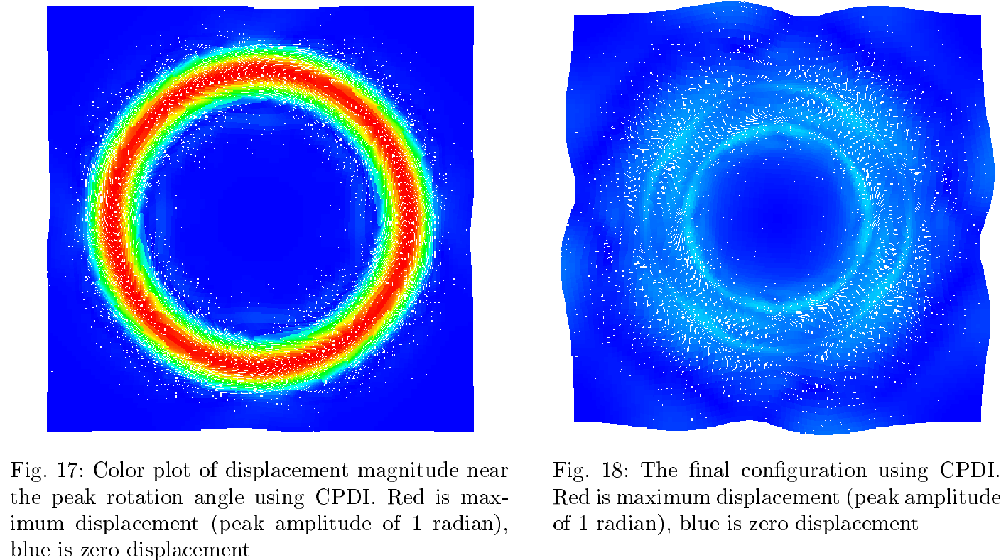
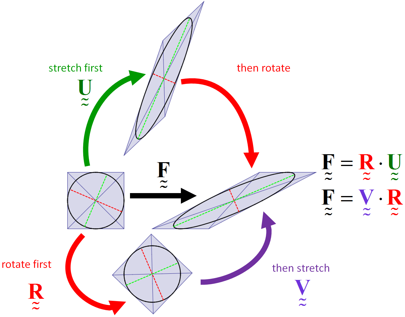
Here are some eye-catching graphics (see the paper itself for details):

2013verificationPic1 Continue reading

F-tables for prescribed deformation

Motion without superimposed rotation

Motion without superimposed rotation

Same deformation with superimposed rotation

Same deformation with superimposed rotation

When developing constitutive models, it is crucial to run the model under a variety of standard (and some nonstandard) homogeneous deformations. To do this, you must first describe the motion mathematically. As indicated in http://csm.mech.utah.edu/content/wp-content/uploads/2011/03/GoBagDeformation.pdf, a good way to do that is to give the deformation gradient tensor, F. The component matrix [F] contains the deformed edge vectors of an initially unit cube, making this a very easy to way to prescribe deformations.

Continue reading

Tangent mapping


These images show the initial configuration of a body (square) and a nonlinear deformation of that body into a curvy shape (to the right of the square).  Overlaid on the actual deformed shape is the so-called tangent mapping at the indicated point.  It coincides with the nonlinear mapping to first-order accuracy.

Continue reading

Illustration of polar decomposition

This posting explains the meaning of a polar decomposition, and it gives two numerical methods for computing it.

Below is shown simple shear of a unit square.  The inscribed circle and the lines from corner to corner should be regarded as painted on the material, so they flow with deformation.  The green and red dashed lines show the principal directions of stretch, which are aligned with the major axes of the deformed ellipse and hence move relative to the material as the deformation proceeds.  In the deformed state (far right), the red and green dashed lines are defined to be aligned with the major axes of the deformed ellipse (far right). The red and green dashed lines in the other states show the material points covered by those green and red lines in the deformed state.

Continue reading

Annulus Twist as a verification test

Illustrated below is the solution to an idealized problem of a linear elastic annulus (blue) subjected to twisting motion caused by rotating the T-bar an angle \alpha .  The motion is presumed to be applied slowly enough that equilibrium is satisfied.

This simple problem is taken to be governed by the equations of equilibrium \vec{\nabla}\cdot\sigma=0 , along with the plane strain version of Hooke’s law in which Cauchy stress is taken to be linear with respect to the small strain tensor (symmetric part of the displacement gradient).  If this system of governing equations is implemented in a code, the code will give you an answer, but it is up to you to decide if that answer is a reasonable approximation to reality. This observation helps to illustrate the distinction between verification (i.e., evidence that the equations are solved correctly) and validation (evidence that physically applicable and physically appropriate equations are being solved).  The governing equations always have a correct answer (verification), but that answer might not be very predictive of reality (validation).

Continue reading

Tutorial: Visualizing Deformation

If you’ve never heard of a continuum mapping, read our introduction to mappings.

This posting discusses the two most common visualization methods for 3D homogeneous mappings: Showing how a sphere transforms to an ellipsoid and how a cube transforms to a parallelepiped:
Sphere transforming to ellipsoidBox transforming to parallelepiped

Continue reading

Tutorial: multi-linear regression

The straight line is the linear regression of a function that takes scalars (x-values) as input and returns scalars (y-values) as output. (figure from GANFYD)

You’ve probably seen classical equations for linear regression, which is a procedure that finds the straight line that best fits a set of discrete points \{(x_1,y_1), (x_2,y_2),...,(x_N,y_N)\} . You might also be aware that similar formulas exist to find a straight line that is a best (least squares) fit to a continuous function y(x) .

The pink parallelogram is the multi-linear regression of a function that takes vectors (gray dots) as input and returns vectors (blue dots) as output

The bottom of this post provides a link to a tutorial on how to generalize the concept of linear regression to fit a function \vec{y}(\vec{x}) that takes a vector \vec{x} as input and produces a vector \vec{y} as output. In mechanics, the most common example of this type of function is a mapping function that describes material deformation: the input vector is the initial location of a point on a body, and the output vector is the deformed location of the same point. The image shows a collection of input vectors (initial positions, as grey dots) and a collection of output vectors (deformed locations as blue dots). The affine fit to these descrete data is the pink parallelogram. Continue reading

Publication: On the thermodynamic requirement of elastic stiffness anisotropy in isotropic materials

Measure of anisotropy for Zircon, Quartz, Uranium, Titanium, Hornblende, and Copper.

T. Fuller and R.M. Brannon

In general, thermodynamic admissibility requires isotropic materials develop reversible deformation induced anisotropy (RDIA) in their elastic stiffnesses. Taking the elastic potential for an isotropic material to be a function of the strain invariants, isotropy of the elastic stiffness is possible under distortional loading if and only if the bulk modulus is independent of the strain deviator and the shear modulus is constant. Previous investigations of RDIA have been limited to applications in geomechanics where material non-linearityand large deformations are commonly observed. In the current paper, the degree of RDIA in other materials is investigated. It is found that the resultant anisotropy in materials whose strength does not vary appreciably with pressure, such as metals, is negligible, but in materials whose strength does vary with pressure, the degree of RDIA can be significant. Algorithms for incorporating RDIA in a classical elastic–plastic model are provided.

Available Online:

http://www.mech.utah.edu/~brannon/pubs/7-2011FullerBrannonInducedElasticAnisotropy.pdf

http://www.sciencedirect.com/science/article/pii/S0020722511000024

Publication: A convected particle domain interpolation technique to extend applicability of the material point method for problems involving massive deformations

A. Sadeghirad, R. M. Brannon, and J. Burghardt

Three snapshots of the model with 248 particles in simulation of the radial expansion of a ring problem using: (a) CPDI method and (b) cpGIMP

A new algorithm is developed to improve the accuracy and efficiency of the material point method for problems involving extremely large tensile deformations and rotations. In the proposed procedure, particle domains are convected with the material motion more accurately than in the generalized interpolation material point method. This feature is crucial to eliminate instability in extension, which is a common shortcoming of most particle methods. Also, a novel alternative set of grid basis functions is proposed for efficiently calculating nodal force and consistent mass integrals on the grid. Specifically, by taking advantage of initially parallelogram-shaped particle domains, and treating the deformation gradient as constant over the particle domain, the convected particle domain is a reshaped parallelogram in the deformed configuration. Accordingly, an alternative grid basis function over the particle domain is constructed by a standard 4-node finite element interpolation on the parallelogram. Effectiveness of the proposed modifications is demonstrated using several large deformation solid mechanics problems.

Available Online:

http://www.mech.utah.edu/~brannon/pubs/7-2011-SadeghiradBrannonBurghardt-NME.pdf

http://onlinelibrary.wiley.com/doi/10.1002/nme.3110/abstract

Publication: On a viscoplastic model for rocks with mechanism-dependent characteristic times

A. F. Fossum and R. M. Brannon

Rate Dependance

This paper summarizes the results of a theoretical and experimental program at Sandia National Laboratories aimed at identifying and modeling key physical features of rocks and rock-like materials at the laboratory scale over a broad range of strain rates. The mathematical development of a constitutive model is discussed and model predictions versus experimental data are given for a suite of laboratory tests. Concurrent pore collapse and cracking at the microscale are seen as competitive micromechanisms that give rise to the well-known macroscale phenomenon of a transition from volumetric compaction to dilatation under quasistatic triaxial compression. For high-rate loading, this competition between pore collapse and microcracking also seems to account for recently identified differences in strain-rate sensitivity between uniaxial-strain ‘‘plate slap’’ data compared to uniaxial-stress Kolsky bar data. A description is given of how this work supports ongoing efforts to develop a predictive capability in simulating deformation and failure of natural geological materials, including those that contain structural features such as joints and other spatial heterogeneities.

Available Online:

http://www.mech.utah.edu/~brannon/pubs/7-2006FossumBrannonMechanismDependentViscoplasticity.pdf